
Keyboard Shortcuts
ctrl + shift + ? :
Показати всі комбінації клавіш
ctrl + g :
Не доступний для безкоштовних груп.
ctrl + shift + f :
Знайти
ctrl + / :
Сповіщення
esc to dismiss
Лайки
Пошук
Step by step on measuring inductor and self resonance
|
Have watched several videos on this and they all seem to leave out most of the setup. Looking to measure inductance but most interested in self resonance frequency. Resonance will be about 2 MHz I am guessing. Have it across Port1/S11 as seen in the videos but don't have display of anything like in the videos. I have looked at the Absolute Beginners Guide but doesn't cover this.
|
|
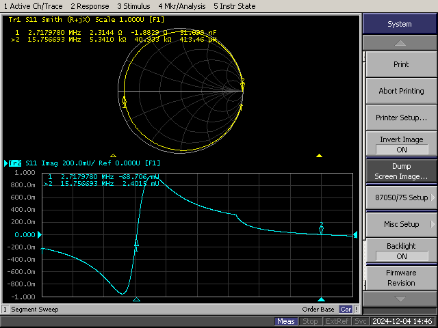
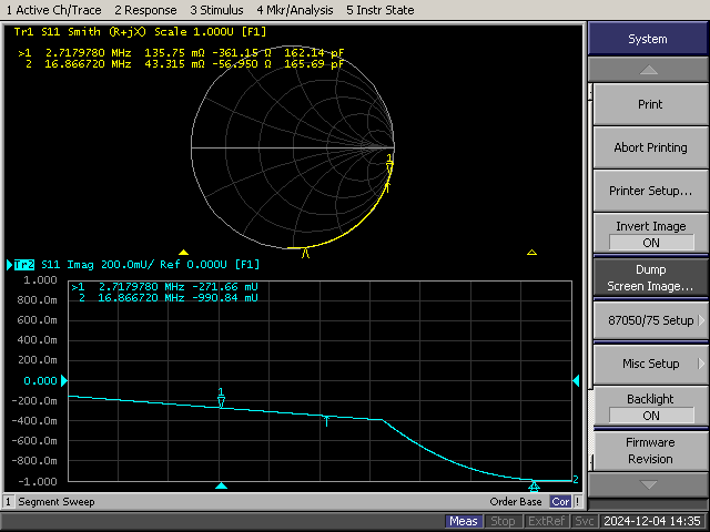
Hi! I sent a post showing how to measure resonance and self resonance and I calculated all parameters of a resonant circuit using almost any VNA. The self resonance is the parallel resonance when you connect a series LC to VNA port. The resonance conditions becomes when the imaginary part of S11 becomes zero at a determined frequency… in the attached picture there are both the serial resonance frequency on marker 1 and parallel on marker 2. Parallel resonance result of parallel connection between L and Cp with is the parasitic capacitance , this is the self resonance frequency. The method is absolutely sensitive to calibration I recommend very good standards.
переключити цитоване повідомлення
Показати цитований текст
I don´t know about your application but self resonance are very unstable depending on dielectric properties of the form ( many times varies with temperature and moisture) and changes every time. The best is to have this resonance frequency very far from working frequency using a very well known capacitor. If you need to know the self resonance to have the value of Cp parasitic capacitance its a very good method but there are other methods that gives it value at the work frequency. Cp frequency dependent. I showed a method to do it on other post , this is derived from a procedure with Q-meter. If you need more details just let me know more about your interest. Ing. Patricio A. Greco Laboratorio de Calibración ISO 17025 AREA: RF/MW Gral. Martín Rodríguez 2159 San Miguel (1663) Buenos Aires T: +5411-4455-2557 F: +5411-4032-0072 www.servicios-electronicos.com.ar On 10 Dec 2024, at 15:09, jskinner58 via groups.io <jskinner58@...> wrote: |
|
I suspect your problem is not your setup (set 2 traces, one to LOGMAG and the other to Smith Chart) but rather your ability to interpret the Smith Chart. Suggest you search YouTube for "Smith chart tutorials" and ground yourself on those. Most of these videos consider a single point ONE FREQUENCY as it appears on the chart. Once you realize all the lines traced on the chart are just a collection of individual points tracing positions on the chart for each frequency in the range of frequencies you are sweeping, it will cease to be a mystery
|
|
On Tue, Dec 10, 2024 at 10:09 AM, <jskinner58@...> wrote:
In order to make a measurement of an inductor's parameters like inductance, reactance and resistance vs frequency and self-resonant frequency the easiest method is the S11 shunt method using just CH0 (Port 1) on the NanoVNA. You need to do the following: - Construct a suitable test jig for the type of device you are measuring (SMD, leaded part, large part etc.) - Connect a short cable from CH0 on the NanoVNA to the test jig - Calibrate right at the test jig where the device under test (DUT) is attached to the test jig - Measure the parameters of interest. For an inductor the self resonant frequency is where the reactance X=0 Measuring inductors and capacitors has been discussed many times in this group and if you search the archives you will find all kinds of discussions about ways to build test jigs, calibration loads for the test jig and how to interpret the results. To get you started here is one I wrote some time ago. https://groups.io/g/nanovna-users/message/20848 Roger |
|
No, although I am not that familiar with Smith charts my question remains the settings and not how to read a Smith chart - I'm not really interested in that chart at this point (but likely will be later on). You gave me two of them: set 2 traces, one to LOGMAG and the other to Smith Chart. And of course, set the start and stop frequency. My issue is also not my fixture that is very short and connected to the right port. I would like to see something like the R and X vs. frequency graph that is next to the last picture in this link that Roger Need posted.
https://groups.io/g/nanovna-users/message/20848 I think I might be able to get the other pieces from this but what other settings are needed? |
|
The Smith Chat is best suited for revealing both resonant frequencies and
values of an inductor. All questions are answered in the single Smith Chart display of the measured data. RESONANCE: Where the trace crosses the centrao horizontal line. This and only this line represents pure resistance on the Smith Chart. And remember the indication of resonance is pure resistance in the total absence of any reactive component. VALUE: Set the cursor to the intended operating frequency for the inductor. Read the value either in + j X or the actual value in XHenries. Dave - WØLEV On Tue, Dec 10, 2024 at 10:35 PM jskinner58 via groups.io <jskinner58= sbcglobal.net@groups.io> wrote: Thanks but I am looking for the specific setting steps to be able to get-- *Dave - WØLEV* -- Dave - WØLEV |
|
On Tue, Dec 10, 2024 at 04:16 PM, JimLS wrote:
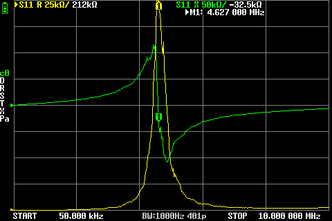
You need to set your traces to read R and X. You have to go into the Display Menu and select a Trace and set it to S11. Then go back and set the Format to Resistance or Reactance. Then set the Scale to have the proper range on the display. Here is an example of an inductor with the traces set to R and X |
|
This would indicate parallel resonance of the inductor as at resonance, the
measurement is indicating a very high resistance. The Smith Chart with the cursor would give you the same information. Dave - WØLEV On Thu, Dec 12, 2024 at 11:48 PM Roger Need via groups.io <sailtamarack= yahoo.ca@groups.io> wrote: On Tue, Dec 10, 2024 at 04:16 PM, JimLS wrote:--is *Dave - WØLEV* -- Dave - WØLEV |
|
I think the best way to measure inductor self-resonant frequency is to place it between the VNA ports and find the transmission loss peak. Using just a single port parallels its capacitance with the inductor. This can greatly affect measured SRF. For example, the measured capacitance of 1.9 pF for port 1 of a NanoVNA-H4 exceeds the 1.2 pF calculated self-capacitance of a 10 uH air-wound coil. SRF will measure 28.7 MHz instead of the true 46.1 MHz. No VNA calibration is needed for this measurement.
Brian |
|
VNA must to be calibrated to perform any measurement. You measure at reference plane no matter the internal impedance of VNA , this is the part of magic of this instrument.
переключити цитоване повідомлення
Показати цитований текст
Ing. Patricio A. Greco Gral. Martín Rodríguez 2159 San Miguel (1663) Buenos Aires T: +5411-4455-2557 ( tel:+5411-4455-2557 ) F: +5411-4032-0072 ( tel:+5411-4032-0072 ) www.servicios-electronicos.com ( http://www.servicios-electronicos.com/ )
|
|
Bonzo , this is a different concept. I say reference plane because is the way to define the measurement point. Its clear that the wavelength is bigger than normal working dimensions in this case , but the problem are the accuracy of measurement and the parasitic components, you can for example add a fixed 100pF capacitor at the VNA port and then perform the OSL calibration after that, over the fixed capacitor you connect another capacitor let 100pF the VNA will measure close to 100pF ignoring the fixed value. This is the VNA calibration. If you use 2 ports to perform a good measurement you need to perform a FULL 2 PORTS calibration to completely define the reference planes or the connection points. Many nanovna has a only 2 parameters , in this case I recommend to use only one port (port 1 ) very good calibrated.
переключити цитоване повідомлення
Показати цитований текст
Other example is a RLC meter , you have an open and short definition to calibrate the instrument and lambda is kilometric… you need to null the parasitic components prior to measure. Again, all depends on your accuracy requirements. Regards, Patricio. Ing. Patricio A. Greco Laboratorio de Calibración ISO 17025 AREA: RF/MW Gral. Martín Rodríguez 2159 San Miguel (1663) Buenos Aires T: +5411-4455-2557 F: +5411-4032-0072 www.servicios-electronicos.com.ar On 13 Dec 2024, at 06:45, Bonzo via groups.io <mora@...> wrote: |
|
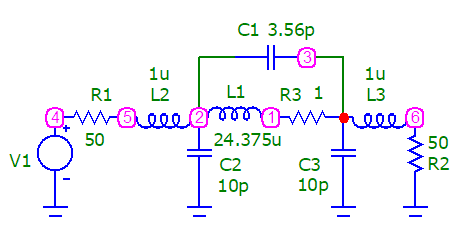
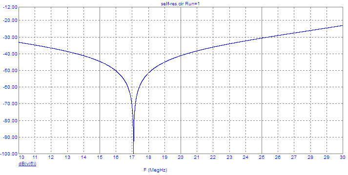
Patricio, thanks for correcting me about calibration nullifying port capacitance. However, I don't think it can nullify stray capacitance to ground due to a fixture or large inductor size. When using a single VNA port, this capacitance appears in parallel with the inductor and alters its SRF. But if the inductor is placed between ports, the capacitance appears from the ports to ground. This does not affect SRF if measured as the frequency of maximum transmission loss. To verify this, I modeled the circuit shown below with stray shunt capacitance and stray lead inductance. C2, C3, L2, and L3 had no effect on the transmission null frequency.
I didn't make the measurements myself, but SRF values near 1 MHz for 2.2 mH inductors differed for single-port and two-port VNA measurements. Though not needed to measure SRF, this writeup describes a method to avoid the effects of stray capacitance when measuring inductor resistance and reactance: https://k6jca.blogspot.com/2020/07/the-y21-method-of-measuring-common-mode.html I've implemented the Y21 method here: http://ham-radio.com/k6sti/stray.zip Brian |
|
Brian: All depends on your accuracy requirement , how you build your calibration standards … for special case of serial resonance you can use 2 ports but you can only measure this frequency. The self resonance frequency is not very useful on RF applications, this is a problem. Is good to know it to have it far from working frequencies.For this reason my approach are more focused to measure other parameters more useful in my point of view. We measure a parameter for a reason, my reason is to design an inductor ro my application or validate a calculus. In general this is one more of parameters under analysis to measure. I posted an example in other subject I will repeat it :
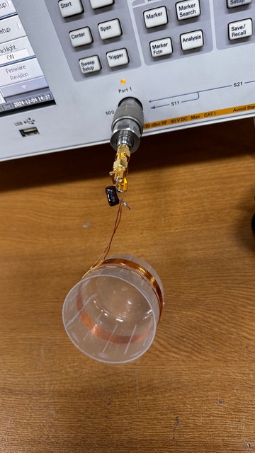
Finally I got some time to perform measurements. I used an E5061A VNA (a nanovna can be used as direct replacement, this is nothing special). I started calibrating my port 1 on SMA male. I build a simple coil over a plastic form and I used a 160pF mica plate capacitor in series. I got a series resonance frequency of fs= 2.718 MHz and a series resonance due pasitic capacitance (Cp) of fp=15.757 Mhz. I used segmented sweep to have more frequency resolution at fs. In my opinion this is a complete set of measurements for example to design an inductor of a resonant LC for a trap or part or any major design. Is interesting the idea to shunt the inductor to measure the capacitor C and then compute the rest of values. Measure only the self resonance would be interesting for a quartz resonator but not for an inductor where you need to know his self inductance value and the Q factor … again : with error on results would be acceptable in your project ? it defines how to measure. A Q factor with an error of 10% is very good for the most applications, this is a reference value , in actual designs it don´t defines the bandwidth of an amplifier for example , modern filters are used now. Ing. Patricio A. Greco Laboratorio de Calibración ISO 17025 AREA: RF/MW Gral. Martín Rodríguez 2159 San Miguel (1663) Buenos Aires T: +5411-4455-2557 F: +5411-4032-0072 www.servicios-electronicos.com.ar On 13 Dec 2024, at 11:44, Brian Beezley via groups.io <k6sti@...> wrote: |
|
On Fri, Dec 13, 2024 at 08:44 AM, Patricio A. Greco wrote:
Patricio, this calculator may interest you for inductor design. Its Q accuracy is within a few percent on average for test coils measured with an HP 4342A Q meter. Worst case Q error is < 10%. It has an optimizer for maximizing Q. It can also optimize a coil for minimum loss in a trap. Much to my surprise, this does not occur at maximum coil Q. http://ham-radio.com/k6sti/coil.htm Optimizing wideband antenna models with coils or traps: http://ham-radio.com/k6sti/wbc.htm Brian |
|
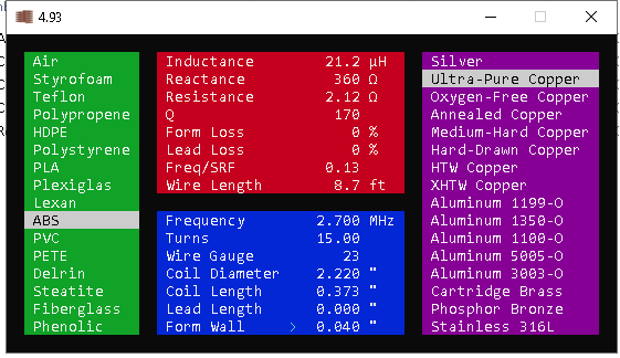
Biran : I downloaded the program and I entered the values of my measured inductor Leq= 21.2 michoH , this is very good result. I suppose the Resistance would be computed via skin effect. For any reason looks like includes the parasite capacitance, this is ok if you want to compute the parallel capacitor for a trap for example or if you with to use the inductor on a circuit design ( for this reason I assigned it to (Leq)uivalent).
переключити цитоване повідомлення
Показати цитований текст
L varies on frequency if you see it goes up this is because you have Cp in parallel then que equivalent Leq= L1/(1- Omega^2 L1 Cp) , L1 is the pure self inductance. Q is ok ! Freq/SRF measured is 0,17 and this is also good. The Q mismatch you mention comes from this error in my opinion , I would need to verify via calculus… but if you read my post you will see that Q goes down if I consider Cp the capacitor used on trap also reduces Q. This is a very good program!! In this example (I posted a capture) I set 2.7 MHz as reference Leq= 21.2 microH , the capacitor to made a trap is C= 163.9 pF we can approximate Cp = 2.81 pF (this is using the program F/SRF ratio) , L= 20,84 microH then If we ignore Cp Q= 169.8 with Cp Q= 166,75. I recommend to perform this calculus and check because in the most of cases the coil Q defines the resonator Q . In my measurement the capacitor Q is ~ 20 times the inductor … you can see when I measured C ESR= 0,13 Ohm… this is not perfect but Q functions like parallel resistors … Qtrap= QL QC/(QL+QC) then Qtrap will go down by 5% Other source of error is because Cp is in general a very bad capacitor , in general results of form dielectric constant and wire enamel… with the most of energy in a lossy capacitor Q goes down… it also affects the self resonance frequency measurement because the dielectric constants varies with frequency for this reason there are another method to compute Cp at the work frequency I shown it in other post. Of course you have optimum values for higher Q it depends on wire length and geometry. Ing. Patricio A. Greco Laboratorio de Calibración ISO 17025 AREA: RF/MW Gral. Martín Rodríguez 2159 San Miguel (1663) Buenos Aires T: +5411-4455-2557 F: +5411-4032-0072 www.servicios-electronicos.com.ar On 13 Dec 2024, at 14:06, Brian Beezley via groups.io <k6sti@...> wrote: |

Повідомлення
Більше
Додаткові параметри
Більше
to navigate to use esc to dismiss