
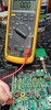
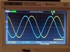
Hello again everyone and thanks to those who responded to my last emails. A few weeks later, many more late nights and still no further ahead, but i will disclose what i have found. First off, thanks for all the suggestions. The QMX is not in practice mode, not in protection mode and the Q507 mosfet is not lifted or broken that i can see. I have .3 ohms continuity between Q507 thru inductor L502, thru T501 and then to the drains of the finals. During transmit , i have .33 v from the drain of Q507 (i hope i have that right? It is the flat portion at the top of it just below L502). Source is 12v and the gate seems to drop only about 500mv or so during transmit. I had been told the threshold was -1.5 to -3v possibly on the gate? I just wish i understood it a little better, like the signal path through an old AA5, LOL. I installed my spectrum analyser at the jumper before the BNC and although no appreciable power out, ALL bands are delivering a almost perfect match with the signal being transmitted through the diagnostics mode. But...-20 to -30 db down in the mud. So very low. But it is there. I am lost for now. Does this make sense to anyone? Thanks for any and all help in advance!
|
|
Release of version 1.2 of ABS solution for QMX+ (Automatic internal antenna tuner, internal battery and internal speaker with audio amp)
12
#ABS
#ATU
#PSU
#QMXplus
Hi, I have released a version 1.2 of the solution. Please refer to the readme front page file at the git repository with details: https://github.com/AC8L/QMX_Plus_Autotuner_Internal_Battery_Speaker/ While I am writing this note - a group buy with 35+ participants is happening for this same version 1.2 - organized by Cal (AD8Q) and Stan (KC7XE). -- 73, Sardar (AC8L, 4K6SA, VA3DUA).
|
|
QMX with iFTx
6
I've read previous post about how to interface these two together. I'm not having any luck. FT8 works perfectly with my laptop running WSTJ FT8 with full CAT control. However, with my iPhone 16 running 18 and my iPad running iPadOS 16, I don't get any signal to decode. I've tried two different camera adapters. The QMX is set to digital and VOX ON. Are there any other settings necessary in the QMX or iPhone I need to change? I love the QMX. I think what it does in such a diminutive package is amazing. Thanks in advance for any advice. 73, Mike NN3I
|
|
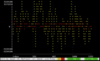
QMX, one of op-amps self-oscillates at 25 MHz (or picks up the system clock?)
11
For some time (several months) I had what I thought was some intermittent QRM, where the band was covered in spikes spaced exactly 100 Hz apart. Here's how it presents itself in the WSJT-X (there are differences on the waterfall, because I was switching bands, and between digital and CW modes). http://arnold.ziffel.one.pl/qmx-wsjtx-swipes.png When it happens, I can still see the band activity below it. It came and went and I didn't think much of it, but today, when testing a new antenna for another band, I noticed the same QRM and started digging. Here's what I found: In a speaker it manifests as buzzing. See the video (and pardon the mess on a desk): https://youtu.be/k8H-BZrNf8I It doesn't change when switching bands. It does change (but not go away) when switching between digi and CW. The same change happens when I enter diagnostics menu (maybe QMX internally switches to CW when entering this menu). It doesn't come from antenna (tested with a disconnected antenna). It doesn't come from the power supply (tested on batteries). It doesn't come from a nearby RF field (tested by walking with QMX around the house without any change). So it's internal to the QMX. I started poking and probing, looking for a bad solder joint or something else intermittent. Everything seemed fine. Then I turned on the oscilloscope and started poking around the input circuity. I found some weird ~25 MHz oscillations on outputs and inverting inputs of two op-amps (two other were fine), both in the same chip (IC406, LM4562). Look (and pardon the mess once again): https://youtu.be/SyRv2tueQlk Mind you, it's not present on any noninverting input. My plan for now is to desolder this IC and see if it goes away (maybe PCM1804 is injecting something -- the signal is also present on its VINR+ and VINR-, not present on VINL+ and VINL-), maybe replace this IC, but it's still strange and puzzling to me. Why is it intermittent? 25 MHz is the system clock, the output QRM is quite stable, which might suggest that this signal is in phase with the system clock -- is it related? Maybe it's some bad decoupling somewhere, or some other element failed and the op amp is good? What am I missing?
|
|
|
|
QMX no transmit on 60M, large B on display between freq and mode
4
I working 60M FTB last night and my QMX was humming along just fine. Then it stopped transmitting and a capital B appeared between the frequency and mode on the display. RX still works fine but the QMX will not transmit in CW or digital but just on 60M - no other band is affected. I did look through the operating manual but did not find anything. 73, Bill NZ0T
|
|
Updated QMX Condensed Menu plus Excerpts from the QMX Operating Manual with Comments
11
The more I play with my QMX, the more impressed I am. The attached QMX Condensed Menu offers only a quick way to locate a particular setting. The Excerpts from the QMX Manual address VFO functions, Frequency Presets, Automated message transmission mode and Terminal Applications. I have included quick access instructions for using the PuTTY terminal emulator for a PC. As Hans has said "it is an easier way to add stored messages or frequency presets." Everything but my comments can be found in the QMX Operating Manual.
|
Good evening! Big thank you to Hans and everyone else in this forum! I had a lot of fun building these kits and I couldn’t have successfully completed them without the folks who ask and answer questions here. I wanted to make this post to thank everyone but also to detail some of the problems I encountered, the equipment I used, and also how I resolved them. This is a long post for anyone who’s interested but TLDR: I built 2 QMX+s and 1 QMX and all three needed new PCM1804s. I purchased a QMX+ in May and a couple weeks later got to work. I had built a couple other kits and antennas previously but this was the most involved so far. I was able to make it through the build and load firmware but I couldn’t run all of the self-tests and the audio was loud static. I didn’t have enough experience or equipment to troubleshoot myself but luckily Jeff Moor W1NC reached out and offered to help. See https://groups.io/g/QRPLabs/message/126274 for my original post. I mailed him my QMX+ and he got it back to me in about a week with several fixes. It had several bad joints, insufficiently scraped enamel, a bad PCM1804, and a bad inductor. Thanks Jeff for your knowledge, experience, and willingness to help the community with your excellent service! I’m extremely pleased with the outcome and my QMX+. I used: A Weller 70W digital soldering iron 63/37 Kester .20 solder 30X/60X loupe https://www.amazon.com/gp/product/B078N34WZR/ref=ppx_yo_dt_b_search_asin_title?ie=UTF8&psc=1 LED Head Magnifier https://www.amazon.com/gp/product/B07T4KPYN2/ref=ppx_yo_dt_b_search_asin_title?ie=UTF8&psc=1 Crescent shear cutter/pliers set from Home Depot A couple of different helping hands type devices Solder wick & plunger type desolderer Flux paste I primarily used the conical soldering iron tip with success but in retrospect, I should have primarily used the wedge tip. The head magnifier with 3x magnification, plenty of light, solder wick, flux, and desoldering tool were critical. The loupe was ok but the head magnifier would have been enough. I ruined the side-cutters on solder wick. Pleased but not content apparently because in July, I purchased another QMX+ so that I could use the lessons learned from the first unit and hopefully successfully build another myself. The kit stayed in the box until my wife & kids went on vacation for about a week. Over a couple of evenings, I had a great time building the kit, using all my new knowledge and experience, but when running the terminal tests, I had bad results on Audio Filter Sweep/RF Filter Sweep/Image Sweep/ADC IQ test. I reworked some of my joints but to no avail. Some example scans, before and after 1804 replacement, are attached. With bad PCM1804 I started diving into groups.io posts and determined that maybe I should invest in more test equipment and that I might have a bad PCM1804 chip. I ordered two more PCM1804 chips (just in case I ruined one). I also ordered a QMX because I was more confident in my kit building skills. In the mean time, I also purchased an LCR meter, a TinySA Ultra (for its signal generator), and an oscilloscope. Probably overkill but I had my eye on them for a while. Over the winter holiday break, I built the QMX. I enjoyed and had more confidence in my build but I had very similar problems to my 2nd QMX+ build during self-tests. During this build, I used a grounding strap/bracelet the entire time so I was pretty sure it wasn’t static discharge related. What are the odds I’d have the same problem twice? I found this post https://groups.io/g/QRPLabs/topic/109639794#msg133769, indicating the PCM1804. I did the diagnostic tests from https://groups.io/g/QRPLabs/wiki/37111 and determined that replacing the PCM1804 was my next step. Luckily I had two new PCM1804’s in stock although I previously intended on only needing one. After doing research here and on youtube for replacing SMDs, I got a ChipQuik kit and a hot air rework station. After doing some tests, I decided I would just use the ChipQuik, which is basically easy-mode for low-skill chip removal. My process was basically, remove the c
|
|
Full Band Coverage QMX+
10
Do I understand the manual, that using all bands is not practical as one has to tweak the band pass filters for specific bands? Example 80-20 only, not 160-6. I see I can select all bands, but my rig won’t cycle through all bands. I purchased this QMX+ used, and just started using it. Thanks for the input. -- Trevor (N0YMA)
|
Hi I'm having problems with QMX version 4. It receives fine, with no issues, but virtually no RF output. I can hear it in CW mode on another rig but it's weak. Using a current limiting PSU set at 11.5v .05 Amps RX .070 Amps TX. In hardware tests mode the SWR jumps around even when the dummy load is connected. Using the Putty terminal emulator the SWR has very random values in every band. Refreshing just comes up with a different set of values between 1 and 10. I have rewound the Really Weird Twisted Sisters Transformer and turned off the SWR protection. Checked the whole board with a microscope any suggestions would be gratefully received. Cheers Paul M0PNN
|
|
QMX Rev 3 - transformer T501 check
Hi Folks, just a small quick question. Have finished output transformer T501 and performing the continuity check in step 17. Continuity of A and B: OK. Between A and B (primary / secondary): out of circuit there is/was no continuity at all. In circuit my cheap DVM measures a very high resistance of a several mega ohm. My DVM does not beep (continuity). Is it normal and ok to have several mega ohm resistance or should I be concerned and search for a problem? VY 73 DE Thomas - DJ1TF - JJ1QPB
|
I will be doing another CW on the air practice session Thursday 01/02/25 . Anyone is welcome. This practice is intended for operators who are new to CW or they need some practice. IT DOES NOT MATTER HOW POOR YOUR CW IS. Mistakes are OK. Poor fists are OK. Slow speed is OK. Really slow speed is OK. This practice is meant for you to improve your CW. I will do my best to adjust to your skill level. Operate at any power level. If several stations show up, I will operate as a roundtable control station. I will do it as a roundtable so everyone gets a chance to transmit. Please listen to my directions. Details: Time - 10:00 AM Eastern Time / 15:00 UTC Band - 40 Meters How to find me - I will find a clear frequency and call CQ. Go to the Reverse Beacon Network and search for my call sign AB8DF. That will tell you what frequency I am on. Tune your station to that frequency and if you hear me give me a call. If there is a QSO in progress, please wait for a break in the action. Then send your callsign. If I hear you, I will invite you to join the QSO and start a roundtable QSO. Reply to this email if you have questions. IT DOES NOT MATTER HOW POOR CW IS Ed AB8DF
|
|
U3S & 10W HF Amp Combo on 160m!
8
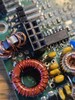
The penny dropped when I realized I could shuffle some QRP Labs gear around and take advantage these winter months running WSPR on 160m. To that end... As you can see I'm running 10W with this current set up. I have a 6dB resistive pad (I think that's the value) between the U3S and the 10W amp. The pad is on the square green perf-board in the photos. The antenna is a long end-fed random wire with 9:1 unun. The U3S/10W HF Amp combo at the bottom is a rig I've posted details about here some time ago (pre-QDX/QMX era). I originally built it up to use it on 8 meters. I never tried getting an experimenter's permit. I've used it on 6m and most recently on 10m & 12m. Here's some views with the lid off: Front to back: Back to front: View of the 10W HF Amp's heatsink mounting. I'm also excited to be using the LDG IT-100 tuner that's been sidelined since I got a LDG AT-200Pro II tuner to use with my "big rig." It's not an auto-tuner but seems to work well with the U3S/amp combo since they are set up as a single-band transmitter. IMO winding a 160m LPF on blue Mix-1 cores is a much better solution than using the stock Mix-2 red ones. I've only had it briefly on the air earlier today and looking forward to how this combo performs. Happy New Year!! --Al WD4AH
|
|
50W Amp - no output
60
#50w
#problem
I could use some help in troubleshooting the amp. But I have a confession to make. I had just finished building the 50W amp kit. I got through the adjustments okay (or so I think) but when I went to measure output I had none. Then I noticed the rookiest of all rookie mistakes. I had connected the amp coaxes to the QCX+ backwards. In other words, I transmitted into the output of the amp and had the dummy load on the input. I guess because it was upside down on my bench, duh. Or there may be some other issue. Not sure what happens when you do what I did. I had keyed the radio a couple times for just a few seconds each and noticed no current draw on the bench supply. There was no smoke or explosions. then noticed the connection issue. Since I suspected no output I connected the QRP Labs 50 Ohm dummyload and checked the RF DCV from the connections provided for that. Nothing coming out at all. 0 Volts. The QCX seems to have survived with over 21VDC measured. Can someone help me save this amp? Bryan, N0LUF
|
|
QMX+ receiver clipping distortion on 40M CW during RAC contest...
7
Hi, I have been playing with my QMX+ over the last month or so since I built it, and it has been behaving quite nicely. Mostly, I have been listening in on W1AW's high speed CW, hoping to one day have enough confidence to actually do my first CW QSO since being licensed a half century ago. W1AW rolls in here very strong. Anyway, the Canadians were having their RAC contest over the weekend, so I thought that I would listen in, and brush up on my experience with contest exchanges. In the beginning, all was well, but as the contest built up steam, and there was a forest of CW signals on the air, I noticed a peculiar thing: The low level signals all had a raspy random noise signature riding on top of their CW tones. If a signal was strong enough to activate the AGC, the noise went away, but for any signal below the AGC threshold, the noise was there, no matter where I was tuned relative to the carrier. At first, I thought the contestants were using poor quality rigs with bad CW signals... but after the number of such noisy CW signals reached the dozens, I had to turn my pointy finger back in my direction. It has to be my QMX+. So, this morning, I investigated the QMX+'s low level signal behavior using a signal generator, to see if I could duplicate the issue. I couldn't. The tone was sweet and pure all the way from S9++ down until it became inaudible. It would seem that it has something to do with large numbers of middling strength signals within the receiver's band. Note that the noisy signals weren't on the threshold of disappearing gracefully into the noise. The signals were all head and shoulders above the background noise. Their tone sounded like it was being clipped, like a guitar run through fuzzbox. They would be easy copy if the tone was clean. So, to capsulize, Only a few strong, or weak signals: clean and pure tone. Lots of middling signals, crackly/clipping noise on top of the CW tones. Ideas? -Chuck Harris - WA3UQV
|
|
Is Hans OK?
15
Everything is very quiet on QMX updates. Just checking whether everything is Ok with Hans. I know he wants to keep the software private to avoid Chinese clones, but I can’t help thinking that if it were all available on GitHub, many Han(d)s would have been working on in the last few months.
|
|
Input voltage for QDX Digital Receiver
9
When ordering an assembled QDX Digital Receiver, the default configuration appears to be for using a 12V power supply. (There is a 9V option when ordering. What is the acceptable input voltage range with the default 12V configuration? Would 9V be too low? Thank you!
|
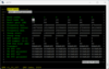
Hi, Got a QMX on the workbench, and pulled up the terminal emulator window to run diagnostics. I'm currently seeing a great yellow trace on the ADC/IQ sweep that looks normal, but a very very erratic red trace. Definitely not a sine wave and absolutely not 90 degrees out of phase. Is this looking synonymous with a PCM1804 failure, or T407? (the trifilar one) being wound wrong? -- Daniel ZL2DTL/ZL4YOTA
|
|
WSJT-X on Raspberry PI 3B and QMX+ unstable
6
The setup of this combination has been working just fine with FT8 and WSPR for a while. All of a sudden, tx stopped working while rx still works, including bandhopping. After resetting and restarting sometimes both tx and rx work, then. again suddenly tx quits. Any advice? Could it be a falty USB-C cable? Hiroki AH6CY
|
Doing some repairs on the QMX I inadvertently used the winding instructions from V2 instead of V1... 23 windings with a 15T tap as opposed to 28 windings and a 19T tap. I didnt realize until I went to check continuity per the v2 manual and had nothing---it still checks out with the V1 instructions, however. Easy to change--but wondered if this was a better design subject to the other additions on the board must have had. Happy New Year to All Scott VY1CO
|
1 - 20 з 18209
Image Name
Sat 8:39am
Sat 8:39am