
Keyboard Shortcuts
ctrl + shift + ? :
Показати всі комбінації клавіш
ctrl + g :
Не доступний для безкоштовних груп.
ctrl + shift + f :
Знайти
ctrl + / :
Сповіщення
esc to dismiss
Лайки
Пошук
Measuring Attenuators
|
Hi All,
New to the group. I have a SAA-2N w/N connectors and cal set. With the necessary adapters (SMA to N etc..) I am not sure I understand if my measurements are correct. Measured (stimulus) from 1MHz - 100MHz; calibrated w/cal set. I then connected a 30db attn and it reads -25.6db @ 30MHz, what is going on? Note: this attn is marked 7-16.5GHz and is an SMA. (I have many of these attenuators and several tests on various units produces nearly the same results) Mike C. |
|
Interesting that it has a low frequency limit. That suggests that there is a DC blocking cap in series with the resistive elements. You might try testing with an Ohm meter between the input and output pins. It is reads open then at 30 MHz you are seeing the effects of a 100 pf or so cap in series. Now up at higher frequencies see if you get closer to 30 dB. A scan at several Hundred MHz might be interesting. Kent
переключити цитоване повідомлення
Показати цитований текст
On Tuesday, August 24, 2021, 05:43:53 PM CDT, Mike C. <mg@...> wrote:
Hi All, New to the group. I have a SAA-2N w/N connectors and cal set. With the necessary adapters (SMA to N etc..) I am not sure I understand if my measurements are correct. Measured (stimulus) from 1MHz - 100MHz; calibrated w/cal set. I then connected a 30db attn and it reads -25.6db @ 30MHz, what is going on? Note: this attn is marked 7-16.5GHz and is an SMA. (I have many of these attenuators and several tests on various units produces nearly the same results) Mike C. |
|
You are measuring far below the specified range of the attenuators at
переключити цитоване повідомлення
Показати цитований текст
7-16.5 GHz. At least that is per your description. *Clyde K. Spencer* On Tue, Aug 24, 2021 at 6:43 PM Mike C. <mg@...> wrote:
Hi All, |
|
Mike,
переключити цитоване повідомлення
Показати цитований текст
Some attenuators are based on a ferrite element that provides relatively constant loss at high frequencies but less loss at low frequencies, I have seen such attenuators with N connectors, but don't recall any with SMA connectors. --John Gord On Tue, Aug 24, 2021 at 03:43 PM, Mike C. wrote:
|
|
On Tue, Aug 24, 2021 at 03:43 PM, Mike C. wrote:
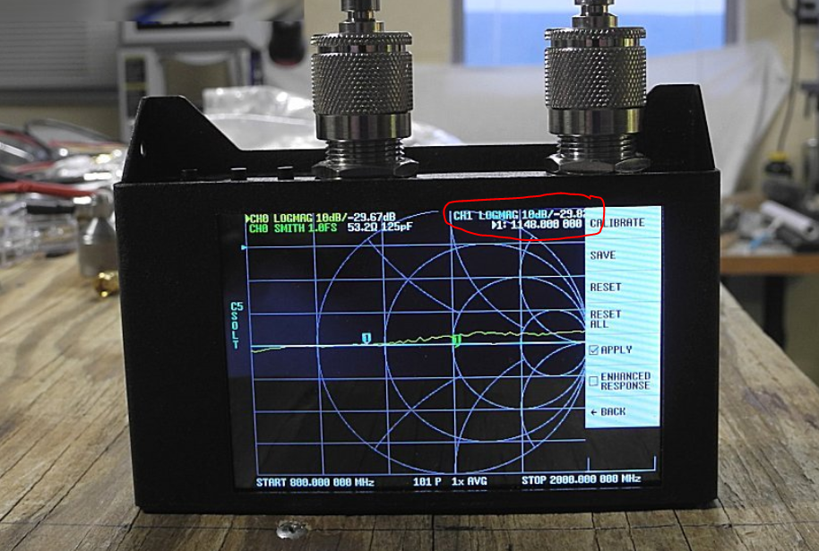
New to the group. I have a SAA-2N w/N connectors and cal set. With theI assume that you are connecting the attenuator between CH0 and CH1 and reading the S21 magnitude in dB. Sometimes new users use make a mistake and use S11 Log Mag in dB which is Return Loss. After you do a full calibration (Open, Short, Load, Isolation and Through) do you get 0 dB with the cable between CH0 and CH1? Why not take a screenshot so we can help you out. You can take one with the PC program NanoVNA Saver or with your camera. Roger |
|
NO I did not go between CH0 & CH1, I'm headed back to the shack to do just that, w/pics, thanks for the advice, I'll reply later.
переключити цитоване повідомлення
Показати цитований текст
Mike On 8/24/2021 7:27 PM, Roger Need via groups.io wrote:
On Tue, Aug 24, 2021 at 03:43 PM, Mike C. wrote:New to the group. I have a SAA-2N w/N connectors and cal set. With theI assume that you are connecting the attenuator between CH0 and CH1 and reading the S21 magnitude in dB. Sometimes new users use make a mistake and use S11 Log Mag in dB which is Return Loss. After you do a full calibration (Open, Short, Load, Isolation and Through) do you get 0 dB with the cable between CH0 and CH1? |
|
OK, did as you all said, hope it's right and here's the link to the pics. (it's easier to put them there then load it to the group, bird shots are extra) :0)
переключити цитоване повідомлення
Показати цитований текст
Mike C. LINK: http://www.mgte.com/VNA/ (haven't used this program in awhile, looks ok though) On 8/24/2021 7:35 PM, Mike C. wrote:
NO I did not go between CH0 & CH1, I'm headed back to the shack to do just that, w/pics, thanks for the advice, I'll reply later. |
|
Hi Don,
переключити цитоване повідомлення
Показати цитований текст
I posted it last night. And yes I'm now (yesterday) measuring from S11 to S21. The attenuators are mounted on S21 and connect to a short jumper that had the SOL made through a female SMA connector back to the VNA. See: http://www.mgte.com/vna/ for detail. Mike C. On 8/25/2021 2:26 PM, Donald S Brant Jr wrote:
Mike: You ARE looking at S21 and not S11, right? What does a thru look like? |
|
Attenuators should be measured with the same setup and philosophy as
filters. They should be placed in a "THRU" or transmission measurement configuration. One could measure them in strictly a reflection manner assuming the reflection at the far unterminated or shorted end is 100%, but the errors will be greater than in the transmission mode. Measured in the reflection mode, the displayed attenuation will be twice the actual attenuation. Dave - WØLEV On Wed, Aug 25, 2021 at 6:26 PM Donald S Brant Jr <dsbrantjr@...> wrote: Mike: You ARE looking at S21 and not S11, right? What does a thru look-- *Dave - WØLEV* *Just Let Darwin Work* |
|
I want to thank all of you for your inputs as I've learned many things in this short time. I'll run a few more attenuators only under narrower freq limits and put the results on my page for easier viewing. It'll be a couple of days, gotta get the car fixed tomorrow.
переключити цитоване повідомлення
Показати цитований текст
Mike C. On 8/25/2021 7:35 PM, David Eckhardt wrote:
Attenuators should be measured with the same setup and philosophy as |
|
In looking at other u-tube videos I see that the VNA only sees the 'plane' where the SOL and thru are terminated. The length of the F to F bullet can probably be calibrated using a few pico seconds but I was only looking for some experience testing the VNA. Besides all of the attenuators I have are marked from 7-16GHz, 1W. Hope that helps.
переключити цитоване повідомлення
Показати цитований текст
Mike On 8/25/2021 9:04 PM, Jim Potter wrote:
That's a good trick, though, for measuring the attenuation of a long cable where one end is a long way from the network analyzer. |
|
Hi Mike,
переключити цитоване повідомлення
Показати цитований текст
I suspect that you've misunderstood the terms S11 and S21. They're not ports, they're characteristics of a DUT (specifically the scattering parameters <https://en.wikipedia.org/wiki/Scattering_parameters>) that the instrument can be used to measure. Roughly speaking: * S21 is the fraction of the power injected at port 1 that is present at port 2. This is typically used for examining two-port filters, of which attenuators are a special case. Formally what is measured is gain, but the usual parameter of interest is insertion loss. * S11 is the fraction of the power injected at port 1 that is reflected at port 1. This is typically used for examining things like terminators and antennas which only have one port. Formally what is measured is the reflection coefficient, but the usual parameter of interest is either of return loss or VSWR. * Similarly for S12 and S22 with respect to power injected at port 2, however NanoVNA designs don't inject power at port 2. If you wish to measure these parameters, you need to swap the connectors. To make matters just slightly more confusing, most NanoVNA designs use "programmer numbering" (perhaps because of port numbers in the underlying firmware/OS?) and therefore label the first port as port 0 and the second as port 1, meaning that S21 is the fraction and phase angle of the power injected at port 1 that is present at port 0, and analogously for S11. - Roland 9V1RT ------------------------------------------------------------------------ On 26/8/21 4:36 am, Mike C. wrote:
Hi Don, |
|
S21 also represents the gain of an amplifier with the input connected to
Port 1 and the output connected to Port 2 (often through attenuators). The gain can be calculated based on all the s-parameters of the circuit, including S12, but is predominantly related to S21. I have used the NanoVNA to adjust several VHF preamps. Zack W9SZ On Wed, Aug 25, 2021 at 10:50 PM Roland Turner via groups.io <roland= rolandturner.com@groups.io> wrote: Hi Mike, |
|
Hi Ronald,
переключити цитоване повідомлення
Показати цитований текст
Yeah, sure did, steep learning curve here, i.e. new gadget. I uploaded 3 pics showing how "I" tested an unknown filter. I'm sure I'll have to make some serious changes soon. http://www.mgte.com/filter/ Again, guys, thanks for your help with this new toy. Mike C. On 8/25/2021 11:50 PM, Roland Turner via groups.io wrote:
Hi Mike, |
|
I have a question about measuring filters below the low end of any Nanovna.
Is it possible to extrapolate both S21 and S11 down to DC on the Nanovna? I am looking for a way to measure some low pass filters I built from 0 to ~20KHz (audio range) without costing a ton of money. I do not have access to a Frequency Response Analyzer. Any thoughts or suggestions would be very much appreciated. Thank you, Ken M. |
|
The minimum frequency of the SAA2 is listed as 50 kHz. The minimum of the
H4 is listed as 10 kHz. It doesn't look like it will work. You might squeeze in the upper edge of your range with the H4, but not the lower end. Zack W9SZ On Fri, Dec 13, 2024 at 6:18 AM Ken Morrow via groups.io <ken.morrow586= gmail.com@groups.io> wrote: I have a question about measuring filters below the low end of any Nanovna.<https://www.avast.com/sig-email?utm_medium=email&utm_source=link&utm_campaign=sig-email&utm_content=webmail> Virus-free.www.avast.com <https://www.avast.com/sig-email?utm_medium=email&utm_source=link&utm_campaign=sig-email&utm_content=webmail> <#DAB4FAD8-2DD7-40BB-A1B8-4E2AA1F9FDF2> |
|
I don’t think the NanoVNA is the way to do this. Not only is the “bottom” end of the synthesized source a bit high, but the whole “what’s the step size of the PLL” thing might bite you.
переключити цитоване повідомлення
Показати цитований текст
I’d look for a cheap USB controlled audio frequency source and a USB AC voltmeter, and then write a small amount of software to sweep the frequency and record the voltages. Almost any digital multi meter would work. As would almost any USB oscilloscope. It’s kind of more of a pain, but you could probably use a USB audio interface and playback sine waves of varying frequencies, and record the responses. Calibration is trickier too. On Dec 13, 2024, at 04:18, Ken Morrow via groups.io <ken.morrow586@...> wrote: |
Повідомлення
Більше
Додаткові параметри
Більше
to navigate to use esc to dismiss